Initial HCS04 Improvement
HC-SR04 Reciever

Figure 1
Improved HC-SR04 Receiver Circuit
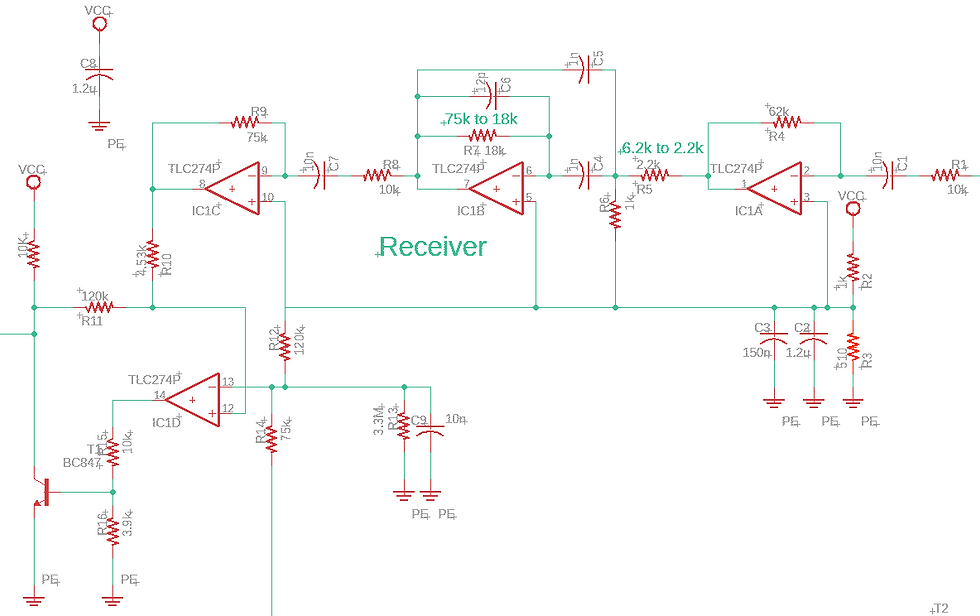
Figure 2
Circuit Differences
The main differences between the original and improved HC-SR04 receiver circuit are the voltage divider tied to the positive sides of the top 3 op-amps, and the bandpass filter resisters.
The main issue with the original voltage divider is that it evenly splits 5V to 2.5V (Figure 1 - R2, R3). In the improved circuit the voltage divider splits the 5V so that ~1.75V are given to the positive side of the amplifiers and the negative side of the competitor. reviewing the datasheet for the LM324 QUAD OP-AMP the maximum voltage is Vcc (5V) - 1.5V. This means the rail-to-rail voltage is not 0V-5V but is 0V-3.5V. With the original voltage divider the middle voltage is not actually centered in the voltage range. By changing R3 that voltage becomes more centered.
For the bandpass filter it is not centered on the source frequency (40kHz). This means part of the signal the ultrasonic sensor revives is being filtered out leading to worse readings. simply changing R5 and R7 to these values (Figure 2) will shift the center frequency to 40kHz.
All following waveforms were made on Multisim not hardware. this it so all values are assumed to be perfect.
HC-SR04 Bode Plot

Improved HC-SR04 Bode Plot

The input signal to the receiver is at 40kHz, however, the original circuits bandpass filter has a center frequency of ~18kHz. By adjusting R5 and R7 to the shown values (figure 2) we can move the center frequency to 40kHz. this allows a stronger signal through the bandpass.
HC-SR04 (Input, Amp1, Bandpass)
.png)
Improved HC-SR04 (Input, Amp1, Bandpass)
.png)
With the changes made to the bandpass filter not only does the signal not get filtered out, but it increases.
HC-SR04 (Input, Amp1, Amp3, Output)
.png)
Improved HC-SR04 (Input, Amp1, Amp3, Output)
.png)
Looking at the signal generated by Amp3 the improved circuit causes the peak voltage to almost double. the output voltage, however, is the same. This is because the voltage limit has been reached (5V). In hardware the output voltage likely wouldn't go above 3.5V as that chip causes a 1.5V drop.
HC-SR04 Output Breakdown Distance
.png)
Improved HC-SR04 Output Breakdown Distance
.png)
The output voltage is now unstable. In the original circuit the output voltage and pulse width breaks down when the source is 10mV peak to peak or less. For the improved circuit it breaks down at 2mV peak-peak. This will cause the new version of the sensor to be able to sense further distances.